
Search
Installation of satellite TV
Advertising
Navigation
Main
Satellites
TV Package
HD Channels
Ultra HD Channels
BISS key
Coverage Maps
Sat Receivers
Installation of satellite TV
Satellite News
Contacts
Search
Installation of satellite TV
Advertising
Navigation
What is DiSEqC, connectivity options |
|
DiSEqC (Digital Satellite Equipment Control) -Protocol communication between a satellite receiver and other devices - such as switches, positioners, etc. To send the signal using a coaxial cable. Mode communication via cable - single or double-sided, to supply power. The standard provides compatibility with conventional switching voltage 13/17 volt and 22 kHz tone. protocol DiSEqC is used to control devices in the receiving system for satellite television. DiSEqC commands are sent through the DC voltage using a frequency of 22kHz tone packages (± 20%) and the nominal amplitude of 650mV (± 250mV) at a supply voltage 13 /18V. Taking into account the cable loss and allowable error DiSEqC-detector device should continue to operate at lower amplitude to 300mV. The standard defines multiple levels, which can run DiSEqC-device. Each level requires a set of generated /executable commands and features. Compatibility levels "down", ie the receiver to support a higher level of working with a peripheral lower level. In practice, this rule is not always. For example, almost all modern digital receiver supports DiSEqC 1.2 (work with positioner) and it does not support DiSEqC 1.1 (to work with an expanded set of switches). Another exception to the rule: any receiver that supports DiSEqC 1.0, the switch must support and Tone Burst - in fact, half the receivers may not work with this switch. There are several options for DiSEqC: The lowest level - mini-DiSEqC or Tone Burst. It does not have "digital" designation and, in fact, not part of the technology DiSEqC, Tone Burst but the device can operate in a single system with "real" devices DiSEqC. Therefore, the standard defines this level as "DiSEqC-compatible" - is compatible with DiSEqC. DiSEqC 1.0 - allows you to switch between 4 satellites; 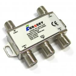
DiSEqC 1.1 - allows you to switch between the 16 satellites; 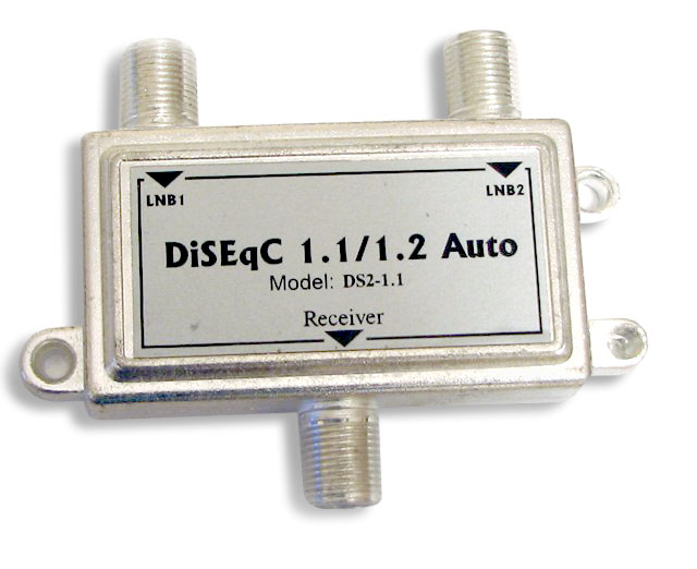
DiSEqC 1.2 - allows you to control the positioner; 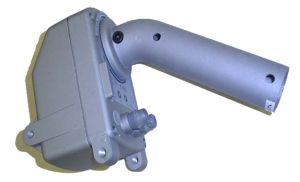
DiSEqC 2.0 - adds a two-way communication mode to DiSEqC 1.0. 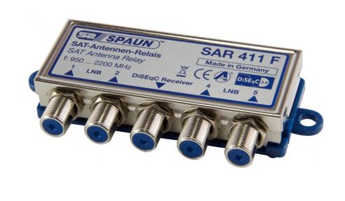
The four variations of the standard have been standardized in February 1998, before the widespread use of digital satellite TV. | |||||||||
Connection options via the DiSEqC heads |
|||||||||
|
The most common configuration is the DiSEqC protocol 1.0 or 2.0 (can be 2 or 4 ports, respectively, can be connected to 2 or 4 satellites), all-purpose converter. Here is the diagram of this connection: • one antenna • one receiver (DiSEqC 1.0) • four universal LNB • One 4/1 DiSEqC switch 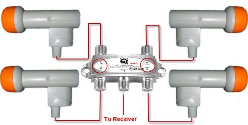
DiSEqC 1.1 - allows you to switch between the 16 satellites. To implement this scheme must be: • Two antennas • one receiver (DiSEqC 1.1) • eight universal converters • Two 4/1 DiSEqC switch • a DiSEqC 1.1 switch 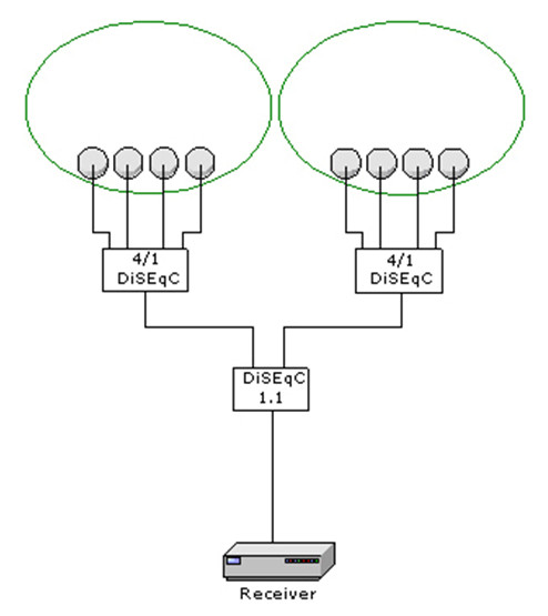
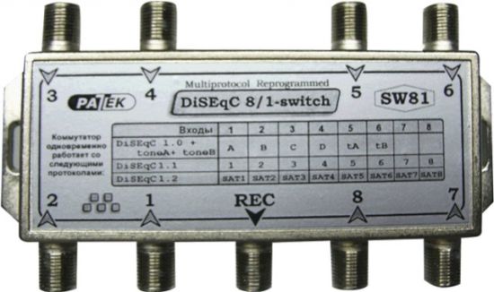
Or use one 8-port DiSEqC 1.1 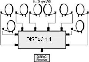
Eight heads can also be connected by a single switch 0 /12V and two 4/1 DiSEqC. To implement this scheme must be: • Two antennas • one receiver (DiSEqC 1.0) • eight universal converters • Two 4/1 DiSEqC switch • a 0 /12V switch • 1 wire cable 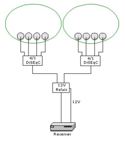
option allows you to connect a 16 satellites! To do this we need: • four antennas • one receiver (DiSEqC 1.1) • Sixteen universal converters • Four 4/1 DiSEqC switch • a DiSEqC 1.1 switch 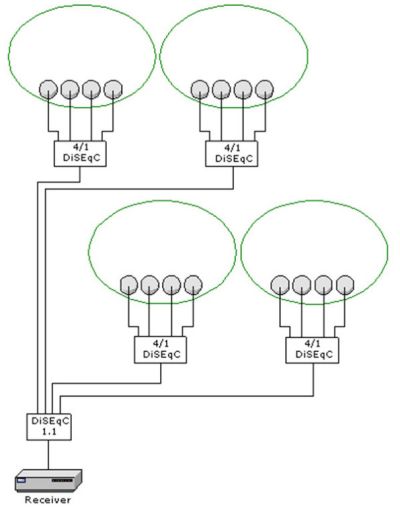
DiSEqC 1.2 - This switch-positioner. It is often embedded within the rotator, allowing you to position the antenna to the satellite. 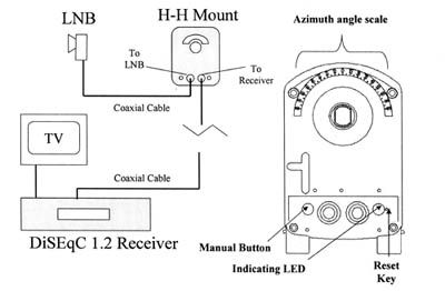
There are also many other options for the construction of systems with different numbers of satellites, heads and switches. All of them are usually chosen based on the specific problem to be solved, and the capabilities of your receiver. If you have a receiver is "old", it is likely that he will not allow to use different options to include heads. Also note that an increase in the number of switches increases and komutiruemy current that can destroy the DiSEqC. Connection option 3 independent receivers to a single antenna 3 satellite: 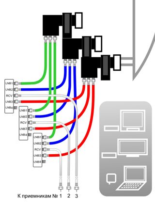
|
| kassim | (2018-04-22 20:15:05) | -13 |
| Good job, keep it up |
